
ILEC GmbH ist seit 1.1.2025 offizieller Hersteller und Händler des GR6b Generatorreglers inkl. OVP (Overvoltage Protection). Das Gerät wurde von Schicke Elektronik entwickelt und bis Ende 2024 produziert. Die Lizenzrechte gingen zum Jahreswechsel 2025 an die ILEC GmbH über.
Produktbeschreibung und Einsatzbereiche des GR6b Generatorreglers
Der GR 6b ist ein kompakter Wechselstrom-Brückengleichrichter/Regler mit Ladekontrollausgang zum Anschluß einer LED oder LED-Lampe. Er ist speziell für den Betrieb an Rotax-, Hirth,- und Solomotoren mit Blei- oder LiFePO4-Starterbatterie ausgelegt.
Er zeichnet er sich dadurch aus, daß die Regelthyristoren in der Nähe des Spannungsnulldurchgangs geschaltet werden, wodurch Spannungsspitzen auf dem Bordnetz minimiert werden.
Ausserdem enthält er eine Überwachungsschaltung (OVP), die den Regler bei Batteriespannungen über 15V abschaltet.
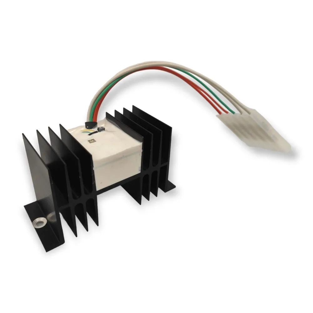
GR6b inkl. OVP –
Generatorregler für Rotax 912/914-, Hirth- und Solomotoren
Preis direkt vom Hersteller
152 € zzgl. 19% MWSt., zzgl. Versand
Technische Daten des GR6b Generatorreglers
| Merkmal | Wert | Einheit |
| Abmessungen (L × B × H) | 115 × 50 × 63 | mm |
| Masse | 0,275 | kg |
| Eingestellte Ladespannung | 14,2 | V |
| Einstellbereich Ladespannung | ca. 13,7 – 14,8 | V |
| Eingestellte Überspannungsabschaltspannung | 15 | V |
| Eigenstromverbrauch (ohne LED) | ca. 0,5 | mA |
| Entladestrom über gelbe OVP-Leitung | ca. 0,1 | mA |
| Minimale Betriebsspannung | ca. 10 | V |
| Ausgangsstrom für Ladekontroll-LED | 20 | mA |
| Maximale Generatorleistung | ca. 250 | W |
Verwendungsgrenzen
Minimale Betriebstemperatur: – 20 °C
Maximale Betriebstemperatur: + 70 °C
Funktionsmerkmale
Beim Einschalten des Hauptschalters leuchtet zunächst die Ladekontrolllampe auf. Sie erlischt, sobald der Generator Strom liefert. Der Regler regelt so, daß die eingestellte Ladespannung der Spannung am dünnen roten Kabel entspricht. Prüfen Sie, ob diese Spannung der tatsächlichen Batteriespannung entspricht! Steigt die Batteriespannung (gelbes Kabel) über 15 V, so wird die Ladung unterbrochen. Die LED leuchtet in diesem Fall auf. Beim Absinken der Spannung unter ca. 14 V setzt die Ladung automatisch wieder ein.
Durch 2 kleine Potentiometer an der Gehäuseoberseite können die Lade- und Überspannungsabschaltspannung wenn notwendig an das verwendete Batteriesystem angepaßt werden. Drehen gegen den Uhrzeigersinn erhöht die Ladespannung.
Das OVP-Potentiometer ist rot markiert und darf nur nach Rücksprache mit dem Hersteller verändert werden!
Wichtige Sicherheitshinweise für Blei- und LiFePO4-Batterien:
Prüfen Sie vor dem Einbau die Kompatibilität von Lade- und Überspannungsabschaltspannung mit der verwendeten Batterie und ob die Batterie für den maximalen Generatorladestrom geeignet ist! Ungeeignete Batterien können überhitzen und/oder beschädigt werden. Speziell beim Einsatz mit LiFePO4-Batterien muß eine Freigabe durch den UL-Hersteller vorliegen.
Einbau des GR6b Generatorreglers im Flugzeug
Der Regler wird mit 2 Schrauben M5 so befestigt, daß die Kühlrippen möglichst vertikal stehen, um eine optimale Kühlwirkung zu erzielen. Der Einbauort sollte so gewählt werden, daß der Regler nicht durch naheliegende Wärmequellen zusätzlich erhitzt wird. Der Anschluss von Generator, Batterie und Ladekontrolle erfolgt über einen 6-poligen Flachstecker, der Masseanschluß über den Kühlkörper.
Achten Sie auf einen guten Kontakt des Reglergehäuses zum Minuspol der Batterie!